

It is unclear how long the mirrors remained on 304 and 305, the last two Labradors with mirrors.
Stability Augmentation System and Pitot Tubes
Both Labradors and Voyageurs use a
stability augmentation system (SAS) to keep the aircraft stable in flight and
in the case of 113s to keep the aft rotors from trying to catch up to the front
rotors. While the helicopter could be
flown with the SAS off, it was much more challenging and certainly not as
smooth a flight. If the SAS kicked off
while in the hover or unexpectedly, it made things potentially dangerous. The two-channel SAS system utilized SAS
(static) ports on both the nose and fuselage of both variants.
Where they differed was in the number and
location of the static ports. Both
types had four ports on the nose, two on the left and two on the right. As
previously mentioned, the location of those on the Voyageur differed slightly
because of the extra nose glass. The
Labrador also had three static ports on either side of the fuselage, the
Voyageur just two. I do not know if the third static port meant the Labrador at
one time had a back up channel or if it was tied to another function?
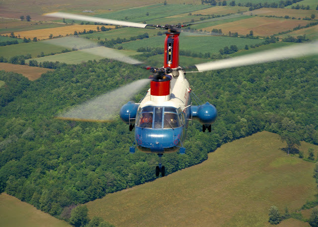

The red circles on the nose of this early Labrador
encircle the SAS system static ports. The large red circles around the ports
will eventually be much smaller. Photo DND
  |
_1.jpg)

The two DND photos above show the three static ports
on each side of the red, white and blue Labradors.
Problems with the cable cutter cartridges prompted
this 103 RU innovation called "SARMUG". Note that the yellow Labrador
still has three static ports on each side of the fuselage. Photo Randy Brown
collection.
Voyageur 313 in variegated camo livery. Note the two
static ports just aft of the door. Photo via Pat Mercer

Voyageur 409 shows the two left side static ports.
There were two more on the right side of the fuselage. Note the emergency exit
door and the silver circle ahead of the nose gear. Photo via Mike Belcher
The pitot static system also utilized a
port to provide among other things, airspeed. When the Labradors were
purchased, they were equipped with two pitot static tubes on the right side and
one on the left side of the fuselage.
They were located above and aft of the cockpit doors. Voyageurs had only the set of two pitot
tubes on the right side fuselage. At
some undetermined point in time the left side single pitot tube was removed
from all Labradors. At the same time,
the number of SAS ports on both sides of the fuselage was reduced from three to
two. On the right side of the fuselage, the SAS static ports were just aft of
the lower Dutch Door and on the left just aft of the bottom of the emergency
door. Photographic evidence reveals
that aircraft 304 was the last to shed the left side pitot tube but only after
it had been through SARCUP.!

Labradors were originally fitted with a single pitot
tube on the left side. Note there is no vent behind the cockpit door. Photo via
Pat Mercer

A close up look at the right side pitot tube common
to both the Labrador and Voyageur. Photo courtesy of Scott Hemsley

The photo above shows the location of the right side
pitot tube. Photo courtesy of Derek Heyes

The above photo shows a SARCUP modified Labrador
sporting both mirrors and the left side pitot tube...neither of which survived
until Labradors were retired. Photo DND
Hover Lights
Labradors as stated earlier use their fully
articulating landing lights in a variety situations from landing, to search or
when in the hover because they can. To
enhance its’ single articulating light, the Voyageur was fitted with a hover
light just aft of the center hatch and slightly to the left of midline. This light, as the name implies, was used
for those situations were the Voyageur was required to hover at night. My presumption is that the light was likely
located here to give the Flight Engineer a better look at the ground or objects
below during SAR procedures. As Voyageurs were mobilized for SAR duties, the
center hatch was used more often to facilitate SAR procedures and was the
position from where Flight Engineers coordinated hoist and sling operations.
Slinging at night would be but one example of where the hover light would be of
use.
|

Unlike Voyageurs, Labradors were not originally
fitted with center fuselage hover lights. Photo DND

Note that the Labrador in the above
picture does not have a hover light in the area of the centre hatch. Photo via
Randy Ward.
Labradors were not purchased with hover
lights and as late as the “Speedline” series of modifications and it seems they
were not fitted with them. As near as I
can confirm through photos, hover lights were installed on Labradors as part of
“SARCUP”.!
Aft Pylon
Likely, the most noticeable difference, to
the educated, between Labradors and Voyageurs is the inclusion of a tail
mounted auxiliary power unit (APU) on the Voyageurs. In addition to a change in the basic profile of the tail, the
auxiliary power unit installation meant relocating, albeit only a matter of
inches, the white aft navigation light.

Photographer Derek Heyes has superbly captured the
shape of the Voyageur's tail. Photo
courtesy of Derek Heyes
|
|
|

The photo above shows how the shape of the tail is
affected by the built-in APU. Photo courtesy of Derek Heyes

Voyageur APU exposed. Photo courtesy Bill Ewing

Close up of APU from left side. Photo courtesy Bill
Ewing
Labradors began life without auxiliary
power units relying on start carts to power up when starting at home bases or
suitably equipped airports. The nature
of search and rescue work, however meant operating unsupported in remote areas
where start carts were a luxury they would have to operate without. Labradors therefore relied on very taxing
and potentially dangerous battery starts.
The solution was to strap a portable APU cart on the ramp. It was not until late in SARCUP that
Labradors were modified with a tail mounted APU. 305 For one was not modified
with a Voyageur tail until after 1980, and was probably one of the last, if not
the last, airframe to be modified with the new tail and APU.


Aircraft 305 sits in front of 103 Rescue Unit's
hangar in Gander, Newfoundland sometime after 1980. Photo Randy Brown
collection
Because of unspecified incidents, Labradors
404 lost it’s rear end shortly after being purchased and was fitted with
Voyageur style tail early. Aircraft 402 however lost its tail in a landing
accident at Coldfish Lake, B.C. in November of 1968. In both cases, while Voyageur
shaped, the new tail did not include the APU.
The opening for the APU exhaust being blanked off and the navigation
light relocated accordingly.
Another aft pylon feature that
differentiated the two variants was the addition of drain covers on the Labrador. Most pictures of Labradors wearing the 400
series numbers reveal that early Labradors did not have drain covers, while
those in300 series numbers always seem to have the covers. The covers were
fitted over all drains on both sides of the aft fuselage. This difference also remained until the
aircraft were retired.!


Close examination of 302's tail will reveal a
Voyageur style tail but no APU. The photo shows 302's SAR Techs (in wetsuits)
transferring a patient to a waiting Buffalo. The author is wearing the tan
flying suit with a dark green flight jacket. Photos Randy Brown collection

Labradors were fitted with drain covers, which
remained in place until their retirement. The covers were on both sides of the
airframe. Photo courtesy of John Davies
Static Discharge Cords
Only Labradors 302 and 303 were equipped
with static discharge cords at the back of the aft pylon, each had four. It appears that the static cords were
affixed sometime after the aircraft were renumbered from the 400 series. Since
other aircraft never received the cords it can be assumed that those that were
so equipped were done so on a trial basis.
It is therefore probable the static cords did not meet expectations.
Given the size, speed and materiel makeup of the tandem rotors, it was likely
hoped that the cords would dissipate some if not all of the static electricity
generated by the turning rotors.

In addition to the four static discharge cords, the
picture shows a red, white and blue 302 with a Voyageur tail. Photo via Mike
Belcher

Aircraft 303 stripped for repainting still wearing
the static cords. Photo via Pat Mercer
The tremendous amount of static caused some
problems for those being hoisted. To dissipate the built up static charge
persons being hoisted down wore a weighted length of light weight chain covered
by rubber tubing that dangled a few inches below the persons feet so the chain
would come in contact with the ground before the person. On one occasion, I was
one of those hapless souls who neglected to attach the chain to the hook…when I
contacted the ground the build up static charge reminded me why we used the
chain. When on the ground, or a ship, waiting to be hoisted back into the
helicopter we made a point of letting the hook touch the ground first so as not
to get unceremoniously zapped.
By the time Labradors had been modified
with tail mounted APUs, only aircraft 302 was left with the cords. 303 When modified for the APU received a
completely new tail resulting in the elimination of the static cords, whereas
302 had received a new Voyageur style tail following its early incident. As noted previously, 302 received the tail,
but no APU…that is until all Labradors were fitted with the tail mounted APU.!

In addition to the static discharge cords, note the
position of the Squadron badge. Photo DND
Hydraulics vs. Electrics (Ramp)
While the ramps of the CH-113 and CH-113A
were for a time functionally different, visually they were almost
identical. It is unlikely the average
modeler will take the time to deal with the comparatively trivial differences.
Labrador ramps were electrically operated
whereas Voyageur ramps were hydraulically operated. The Labrador ramp could be operated using switches located at the
front of the cabin or at the left rear of the cabin, but slightly ahead of the
engines. There were also switches on
the left side, and outside, of the tail below the aft pylon. Once activated the ramp movement, up or
down, was facilitated with screw jacks located one on either of the ramp a few
inches aft of the ramp/fuselage hinge.
Essentially large worm gears, the screw jacks were dark gray, almost
black, in colour.

|
|

Several things in this picture of a Labrador
interior are worth noting if you intend to have your model showing the interior.
Notice the hoist location and cover; the door leading to the cockpit; the lack
of gauges on the SAS closet and the cabin insulation. The hoist above is rigged
to assist in the recovery of a hung up parachutist. Photo Randy Brown
collection
Voyageur ramp movement was initiated by one
set of controls; two control levers, located below the engine compartment and
aft of the ramp/fuselage hinge. The
same levers could be accessed from the inside or from the outside by reaching
through a small hatch. A pair of ramp
actuators that were silver in colour facilitated movement of the ramp. At some point late in the service life of
the Labradors, probably SARCUP, hydraulics replaced some electrically operated
functions such as the ramp and the internal back up hoist.

Voyageur ramp controls, as seen above, were in one
location at the back of the aircraft, but could be accessed from either inside
or outside of the helicopter. Photo Randy Brown collection
The only other ramp difference was the
existence of rollers on ramps of Voyageurs, a continuation of those on the
fuselage floor, which will be discussed, in later paragraphs. Rollers were an Army requirement not
considered for Labradors. When Voyageurs were transferred to the Air Force for
SAR duties, the rollers were at some point removed. A lack of relevant photographs makes it difficult to narrow the
period of their removal down.!

Nice shot of a Labrador ramp and ramp extensions.
Other things in this photo of use to the modeler are the left side drain covers
and the silver hydraulic ramp actuators on either side of the ramp for years
more commonly associated with Voyageurs (Labradors had screw jacks). Photo
courtesy Jeff Wilson

The above photo shows the Voyageur ramp with the
roller channels, but not rollers. Photo courtesy Scott Hemsley
Engine Inlet Screens
Pictures show that Labradors, when
purchased, did not have engine inlet screens. Whether Voyageurs did or did not
is not clear. In any case, both variants were fitted with the same conical
shaped screens early in their service life.
The purpose of the screens was to prevent debris from being ingested
into and damaging the engines. When
looked at from head on it is interesting to note that the inlets screens are
neither exactly conical in shape nor symmetrical when comparing left with right
screens. In part, the asymmetrical
shape is because the sync shaft tunnel is not centered on the top of the
fuselage.

Note the lack of engine inlet covers on airframe
11401. Photo via Pat Mercer

Note the shape of the engine inlet screens and their
position relative to the sync shaft tunnel. Photo Randy Brown collection
In the spring of 1989 as my time on
Labradors was ending, there were discussions regarding new engine inlet
screens. From what I can recall, it
seems the conical screens while effective against foreign object damage (FOD)
had a tendency to ice up enough to reduce airflow to the engines in certain
weather conditions. I believe the
larger screens were thought more likely to cancel out the potential for engine
failure from weather conditions.!

Newly installed "top hat" engine inlet
screens. Photo via Pat Mercer

The above photo shows the right side engine inlet
screen. Photo courtesy Jeff Wilson
Stability Augmentation System (SAS) Closet
At the front of the cabin on the right side
of the fwd bulkhead is the SAS closet.
Unlike their American counterparts, Canadian aircraft had covers over
the SAS bay. Voyageurs SAS closet covers, because of the greater use of
hydraulics, differed from Labradors by having two gauges located on the upper
SAS closet cover.
|


|

The interior look of Labradors changed several times
over the years. The above photo shows the resultant changes. Note the rolled up
blackout curtain to the left of the door leading to the cockpit; the location
of the door brace near the front door; the absence of gauges on the SAS closet.
Photo courtesy Jeff Wilson
Where the Voyageur had the two gauges,
Labradors had a crash axe. In Voyageurs, the crash axe was a few inches below
where it was on the Labs. Moreover,
because the Voyageur differed from the Labrador in that it had a soft blackout
curtain instead of the Labrador’s blackout door, the Voyageur’s map case was
located on the lower SAS closet cover. The map case on Labrador was on the
cabin side of its’ blackout door. The last thing to go on the SAS cover was the
lower Dutch Door brace.!

On the Voyageur SAS closet covers in the photo above
you can see the two gauges, the crash axe, door brace and to the right of the
brace the map case. A portion of the
black out curtain can also be seen. Photo courtesy Scott Hemsley
Black out curtain/door
As mentioned in the foregoing paragraph
both variants utilized, albeit different style, black out methods to allow Para
Rescue personnel (eventually Rescue Specialists then SAR Techs) to prepare for
an mission or to carry out medical care on patients in a lit cabin while not
negatively affecting pilot night vision in the cockpit, a light barrier was
required. In the Labrador, the barrier
was a door, while on the Voyageur a zippered blackout curtain was employed.
Labrador blackout doors were eventually removed and replaced by the more
practical blackout curtain.!

The map case can be seen on the lower part and back
of the padded and closed door leading to the cockpit. Photo Randy Brown
collection
Cabin Insulation
Yet, another feature that will likely be
ignored by all but the most thorough of modelers, especially in larger scales,
is the cabin insulation. The most
noticeable difference between the insulation on one variant compared with the
other was colour. Early insulation on
the Voyageur was a very pale green compared with a light to medium gray on the
Labrador. The two different insulation
materials do not lend themselves well to scale modelers so will be avoided,
that said, as insulation wore out and was replaced the difference in insulation
slowly disappeared until eventually all insulation was that of the Labrador.

The picture above clearly captures the difference in
colour of the original Voyageur insulation and that of Labradors. The lighter
green insulation used originally in Voyageurs can be seen on the cabin ceiling
and wire/tubing tunnel covers. The walls are adorned with gray replacement
insulation more commonly associated with Labradors. The aircraft above is from
103 Rescue Squadron (Gander, NL) and is participating in Search and Rescue
Exercise (SAREX), thus the reason all eyes are in the windows. Photo DND
The insulation on either variant is
straightforward. The criss-cross pattern often associated with aircraft
insulation is incorrect for Labradors and Voyageurs. On these helicopters, the
insulation was nothing more than a padded material that did not have
cross-stitching. It was held on to the airframe in one of two manners and
in some cases or locations both. The older method (although still used to
a degree) was to use snaps. The second method was Velcro. Here is where
it could get tricky modeling insulation if you were really into the accuracy
thing. Before, an airframe arrived back at the unit (after being in
Arnprior for thorough maintenance) the insulation was installed (or
reinstalled) before fixtures and fittings were put back into the cabin.
Everything...including the radio boxes, which were set into a position
essentially recessed behind the insulation, had covers. It did not take long
for these covers and other similar covers to go missing leaving structural
components including the outer skin, exposed. Also behind the insulation were
the 28 volt outlets, heating duct controls and for a time the hoist controls.
Access to these areas was frequent and the constant tugging and pulling of the
insulation resulted in Velcro strips glued to the airframe coming off leaving
the insulation hanging. It would only be a nuisance for so long before someone
would "store” a part of the insulation, notably the blanket in front of
the hoist station, for safekeeping.
To model the insulation, two methods
I would consider are simply to paint the area using a “tromp loie” effect or
tissue painted with a white glue/water mixture. In my opinion detailing the
insulation is easier and less tedious that adding the wires, tubing and pipes
of the Lab/Voyageur, although it would certainly be less dramatic.

The 424 Transport and Rescue (T & R) Squadron,
Trenton Voyageur trains CASARA spotters. Wire/tubing tunnels unique to the
Voyageur can be seen on both sides of the cabin at a point where the walls
transition into the ceiling. Photo courtesy of Terry Cooper

Looking at the point were the cabin walls merge into
the ceiling, it is clear there are no wire/tubing tunnel covers in the
Labrador. Photo courtesy Jeff Wilson
A difference in insulation that did not
disappear was the use of wire and tubing covers in the Voyageur. The pictures
above clearly show the covers, which ran the length the fuselage, on both sides
of Voyageurs only.!
Pilot Seats
A difference that is seldom mentioned is
the difference in seats styles, including the difference between the pilot
seats of the Labrador and Voyageur. On the left is the Labrador seat, on the
right the Voyageur seat. This is a difference I believe remained for the life
of the aircraft.


Flight Engineer Seat
While the Flight Engineer seat in the space
between the cockpit and cabin differed in the two early 113 variants, there was
no difference by the time SARCUP was completed. For the time being, I lack photographic evidence to support my
recollection that the seats once differed, however after conferring with an FE
friend, I have some specifics.
One of the things I remember well was that
the Voyageur FE station was considerably less comfortable than the Labrador
version. This is due to a couple of things. As can be seen in the pictures
below, the Voyageur station had the rather large cabinet on the left side that
the Labradors did not. The cabinet reduced the width of the space by several
inches. The purpose of the cabinet is two fold. What can be seen at the top of
the cabinet is the circuit breaker panel. On the Labrador the breaker panel is
behind the copilot’s seat, a portion of which can be seen in the picture on the
right and below.
The second purpose of the cabinet is that
it housed some of the extra hydraulics the Voyageur used. Of particular note is
the hydraulic hoist used in Voyageurs was situated directly above the
companionway door leading to the cockpit and where the FE sat. Originally,
Labradors used an electric hoist so did not need the bulky cabinet. As part of
the many modification, both variants used the externally mounted, hydraulically
operated hoist with an internally mounted hydraulically operated hoist as a
back up. This required Labradors to be modified to accept the hydraulics and
thus the new hydraulics cabinet.
|


While the two pictures above show the Flight
Engineer (FE) seat on a Voyageur, there is little difference on a Labrador. The
picture on the left shows the FE seat stowed on the right side of the tunnel.
The picture on the right shows the back of the FE seat hanging limply on the
aft portion of the breaker box (to the left of the coiled intercom cord). Both
photos courtesy of Scott Hemsley
The second reason the Labrador FE seat was
more comfortable, is that the Lab seat was wider, had the same tube frame
structure for not only the seat, but the seat back as well, which was
sufficiently padded for comfort. As can be seen in the picture above right, the
Voyageur seatback was basically a strap. While not a significant difference,
the final difference in FE seats is that the Voyageur FE seat was stored on the
right side of the companion way, the Labrador seat was folded up on the left
side of the companion way.
Spotter Seats
There is on the other hand plenty of
documentation to demonstrate the difference in spotter seats. The seats located at the forward search
blisters were an essential part of SAR Labradors, but unnecessary weight and
bulk in the troop carrying Voyageur.
Voyageurs, as one might expect of an Army transport helicopter made use
of troop seats when carrying personnel.
Troop seats were of the standard red nylon variety typical of all
Canadian aircraft.


The picture on the left above and the drawing on the
right above show the original seat fitted on the Labrador. The seat was less
crashworthy than its' replacement, due in part to its' short back. Photo Randy
Brown collection


While Labrador seats were originally painted black,
they like all Voyageur seats were predominately gray. Seat covers on both style
seats varied from green, to red or orange. Photo courtesy Scott Hemsley
When Voyageurs became part of the Air Force
SAR inventory, proper spotter seats became a necessity, however where to get
seats? The answer, I believe, was in
the Argus. The Argus seats, if in fact
they are Argus, seats were taller and more robust than those of the Labrador,
so it made sense to eventually replace the Labrador seats as well. When the Labrador seats were replaced and
the source of the new seats is unclear, but I suspect the source of the seats
was the Argus, which was being replaced by the Aurora.!
Box seats
Along the right cabin wall behind the right
spotter seat were three box seats that doubled as equipment storage. Technically, the boxes differ, but in size
and colour only so from a modelers perspective hardly worth the effort to
acknowledge the difference. The main
difference in the seats was the colour of the cushions and the boxes
themselves. Along the wall, both variants used the back of the red nylon troop
seats.
Labrador seat cushions arrived from the
factory covered in red nylon. Voyageur
seats were locally manufactured, accounting in part for the different size, so
the cushions were covered in whatever material was locally available. In my experience, red, blue or tan
leatherette were common.
The locally manufactured boxes used in the
Voyageurs were made of sturdy gauge aluminum that was left unpainted for
several years. Labrador boxes were
painted the same colour gray as other interior features.!

As can be seen in the above photo, the two back
seats have two lids each, while the forward most box has a single lid. Photo
courtesy of Derek Heyes
Hot Cups
Internally, for the most part modelers will
consider several differences inconsequential.
For the sake of a few lines of text, I have included them for that
modeler who might want to build a larger scale version or the modeler who might
want to do a cutaway version for example.
At the time of purchase, neither the Lab
nor Voyageur had hot cups to heat water for a hot drink on the all too frequent
long flights or cold days. Originally
fitted in the C-47 Dakota, the Labrador was the first SAR helicopter to be
fitted with hot cups. Two cups were
installed one above the other on the right side of the cabin wall immediately
ahead of the search blister. The bottom
cup was only inches above the floor and just a couple of inches ahead of the
station inline with front of the front search blister.
As the Voyageurs integrated into the SAR
fleet, crews heated their hot water in a single hot cup attached to the
aircraft electrical system by a long umbilical power cord. The single hot cup was eventually replaced
by two hot cups attached to the front of the radio rack that was eventually
installed ahead of the left side SAR Tech chair on the left side of the
cabin. To the best of my knowledge,
Labrador hot cups were eventually relocated to the left side of the cabin as
well.!

The hot cups were affixed to the front of the radio
rack on the left side of the aircraft slight aft of the left side emergency
door. Photo DND
Section 3
Operational Differences
Operational differences will look at
equipment or features of the Labrador and Voyageur from an operational
perspective. Because both of these
aircraft served in the search and rescue role for most of their existence the
majority of the discussion will focus on SAR.!
Antenna
It is in all probability doubtful that the
antennae on one aircraft matched exactly that of another such was the pace of
change with radios and navigational equipment.
For this reason alone I will not get too much into the various antennae,
save for two notable examples; High frequency (HF) and Search and Rescue homing
(beacon). It is incumbent on the
modeler to check photos carefully if accuracy is your aim with respect to antennae.
I will where possible be identifying the various antenna, if the antenna is
identifiable.
|

|


At the time of the helicopter purchase
radios and navigational aides were barely out of infancy compared to what
aircraft of the ‘70s, ‘80s and beyond would have. Perhaps one of the most important pieces of equipment was, and
maybe still is, is the High Frequency (HF) radio. HF gives aircraft crews the ability, under the right conditions,
to transmit/receive to and from another station anywhere in the world. HF radios have been a part of the Labrador’s
communications arsenal since the earliest days and continued to be so until
retirement. Pictures of HF radio antennae as they changed over the years
illustrate changes in HF antenna design and location that are representative of
antennae evolution for all radios and navigation aids. One picture in Mr. Pat
Martin’s book shows 305 with a blade HF antenna painted green whereas the more
common colour was blue. Yet, another picture shows a yellow aircraft carrying
the blade antenna on the left side, which became the standard. In Pat Martin’s
newest book, “Royal Canadian Air Force – Aircraft Finish and Markings 1947-1968
– Volume 2”, there is a picture of a RWB Labrador with the blade antenna just
aft of the front door on the right side of the aircraft…I am of the opinion
that this was part of HF trials. To further illustrate my point regarding
antenna location, a couple of pictures show Labrador 301 with the final version
of the HF antenna in the same location as the HF antenna on Voyageurs. A picture
from a later date shows the HF antenna on 301 in the standard location for
Labradors. It is unclear why there is a difference in the HF locations on the
later date Labs and Voyageurs, but it is a certainty the difference was
maintained until retirement.

The object of our attention is actually Labrador 405
in the background. Of note is the green HF blade antenna on a Labrador still
wearing its' 400 series number. Photo DND

The HF blade shaped antenna was fitted to the
fuselage just aft of the left side emergency door and far enough ahead of the
front search blister so as not to be too restrictive to the spotter on the left
side during searches. Photo courtesy of Dave Marshall

Pre-SARCUP Labrador 305 sports a yellow paint
scheme, a yellow HF blade antenna and black "RESCUE" titles. Photo
via Pat Mercer
I seriously doubt that even the most ardent
of modeler is going to model the instrument panel and console to follow the
changes in the various radios and nav aids, indeed it might be impossible in
scales smaller than 1:48, however the change in antennae is doable. One of the
earliest antennas that present the modeler with a manageable challenge is
SARAH. Radios early in their developmental stages were comparatively
unsophisticated and of limited function; so much, so that it was uncommon for
downed aircraft to be able to communicate with searchers. Additionally,
searchers lacked any real technological means to locate the downed aircraft.
“SARAH”, (search and rescue homing beacon) changed that.

The photo above shows the positioning of the HF
antenna overtop of the lightning stripe on the Voyageur. Photo courtesy Derek
Heyes

Unlike the Voyageur, the Labrador's HF antenna is
positioned above the lightning stripe. Photo courtesy Jeff Wilson
Unfortunately, I have virtually no
information on early Voyageur antennae. This is particularly so for the early
years through to the time when Voyageurs were painted yellow and modifications
were being undertaken to make them SAR capable.!

The above photo gives you a close look at the right
side SARAH antenna. A second identical antenna is located in the same position
on the left side. Photo Randy Brown collection

In addition to the left side SARAH antenna, the
above photo shows the forward HF antenna mast and the HF antenna entering the
fuselage through the lightning stripe. Photo via Pat Mercer

Floors
Voyageurs were purchased by the Army to
move equipment and personnel from rear echelon positions to positions closer to
the action. The distance between the
two positions was relatively short so as has been noted Voyageurs were not
fitted with long- range fuel tanks. If
greater range was needed internal, fuel bladders could be added a modification
that took, as I understand it, about three years to implement. Operationally, the role of the Voyageur was
essentially that of a transport.
To accommodate expedient loading and
unloading the floor of the Voyageur was more robust than that of
Labradors. The center panels of
Voyageurs were built to handle heavier loads of vehicles and military
pallets. On either side of the center
panels was a row of rollers and outside of the rollers were vehicle tread ways
designed to handle rubber-tired (as opposed to tracked) wheel loads.
Rollers were in place the full length of
the fuselage and ramp. The cargo ramp
also had two smaller folding ramps that could be positioned at any point along
the width of the ramp to accommodate a variety of different sized loads.

Although the rollers have been removed, the roller
channels are clearly visible. At the
end of and to the outer edges of the ramp are the two ramp extensions. Photo
courtesy Scott Hemsley
The floor of Labradors was unlike all other
CH-46/KV-107 models in that the construction of the floor was lighter and
lacked the rollers. At some point in
their SAR careers rollers were deemed expendable and removed from Voyageurs,
although the roller tracks and small ramps additions remained.!

The Labrador did not have rollers as can be seen on
the ramp above. In the above photo it also easier to see the two ramp
extensions. Photo courtesy Jeff Wilson

The above photo gives us a clear look at the
rollers. Photo DND
Hoists
In keeping with the Army’s, transport role
for the Voyageurs the CH-113A was equipped with a robust hoist that was geared
primarily to “pull” heavy equipment and vehicles into the cabin. In addition to the slow rate of operation,
the hydraulically operated hoist used a shorter thicker cable than that of the
SAR Labradors.

Even after external hoists had been installed,
external hydraulic hoists were retained as a back up on both variants. Photo courtesy Scott Hemsley
While the Voyageur was a credible secondary
SAR resource, it still lacked an efficient rescue hoist. As Voyageurs were
absorbed by the Air Force into the primary SAR role their limitations where
recognized as a serious impediment since the Voyageur hoist was used through
the floor at center of the fuselage.

Master Corporal Dave Aalto of 413 Squadron
demonstrates use of the "Sky Genie" friction descent device and the
Voyageur's center hatch hoist. Photo Randy Brown collection
Designed for search and rescue, the
Labrador counted on versatility to ensure reliability. While the Labrador had only one hoist, that
hoist could be used in different configurations. With a longer hoist cable, the electrically driven hoist was
geared to operate faster than its’ Army counterpart. The 113-hoist cable was routed through a series of three pulleys
from the forward bulkhead aft to the ceiling, to the left side of the cabin
opposite the open door and through a bell housing on the internally mounted
(Swedish) boom hoist. The Swedish boom,
was then extended forward through the open doors to facilitate a rescue procedure.
|

|

In addition to the location of the Labrador's hoist
and the cover on the bottom of the hoist, note the position of the bell housing
on the Swedish boom when the boom is in the vertical position. The hoist above
is rigged for para-drops. The fact the parachute anchor line cable runs along
the cabin wall indicates the photo is late 1980s at the earliest and more
likely 1981. Photo Randy Brown collection
Occasionally, as might be expected, the
infrequent problem with the Swedish boom necessitated use of the hoist through
the center hatch. Like the Voyageur,
the cable was routed from the forward bulkhead along the center of the ceiling
to a hard point and pulley system directly above the hatch.

With the Speedline modification program,
all 113s were equipped with a much faster hoist with a longer cable. The new hoist was capable of carrying 600
pounds up or down compared with the 600 pounds up and 300 pounds down for the
older Labrador hoist. By the time, all
aircraft were equipped external hoists both Labradors and Voyageurs utilized
hydraulic hoists as a back up to the Speedline upgrade.
One last aside, the earlier electric hoist
used by the Labrador was more compact and was affixed to the cabin bulkhead
above the companionway leading to the cockpit. While it was not centered exactly,
it was more centered than the hydraulic hoist of the Voyageur. The reason lies
in the size of the hydraulic hoist and the extensive array of hydraulic lines.
A lack of space to accommodate the hydraulic lines, the only option was to move
the larger Voyageur hoist slightly to the left.!

The 1971 photo
above shows both the position of the lower Dutch door and the Swedish boom in
the hoisting position. Note the position of the bell housing during hoisting.
Photo Randy Brown collection

The photo above gives you a good look at the
multitude of lines running to and from the external hoist. Photo courtesy Derek
Heyes

Scott Hemsley gives us a good look at the hoist from
below. Photo courtesy Scott Hemsley
Water Dam
Amphibious helicopters, both the Voyageur
and Labrador exercised regularly and often in the water. At times both variants conducted water borne
procedures that necessitated opening the ramp and upper hatch. To keep water from out of the cabin and from
sinking the aircraft, a water dam was used.

Once a routine procedure for SAR Labradors and
Voyageurs, the boat launch and recovery procedure was eventually phased out.
Here Rescue Specialists exit the helicopter as they prepare to lower the
outboard motor. Photo Randy Brown Collection
The dam of each variant differed only
marginally, and perhaps not enough for the modeler to notice. Firstly, the dams were constructed of
different materials and finished differently.
The Labrador ramp was made of lightweight metals and finished in the same
gray as the interior of the cabin. The
Labrador dam, when in place at the end of the bench seats and ahead of the ramp
was no taller than the box seats.
In the Voyageur, the ramp was made of wood
and finished with a clear varnish or lacquer, so looked like a finished sheet
of plywood. Voyageur dams were slightly
taller than that of the Labrador with the top of the dam above the top of the
box seats.
Another noticeable difference between the
dams of these two aircraft was their storage location when not in use. It was common for the dam to be in place,
especially when the aircraft was on SAR standby, however this was not a hard
and fast rule.

At one time, the two variants stored their water
dams in different locations, but that eventually changed and both stored the
dam on the left side of the ramp inner fuselage. Photo courtesy Jeff Wilson
On either bird, the dam was occasionally
stored behind the stretchers at the rear of the cabin, however the more usual
storage location was on the ramp area sidewalls, the Lab dam stored on the
right side the Voyageur’s stored on the left side. Since the Voyageur had a hydraulic hand pump at the forward end
of the ramp on the right sidewall, placement of the dam in this location was
impractical, so the same location on the left side was selected.

In later years, the water dam was stored in the same
location on both variants. Photo courtesy Jeff Wilson

Although the Labrador above has the hydraulic hand
pump in the same location as a Voyageur, the style of the handle is somewhat
different. Before being modified with a hydraulic ramp, Labradors stored the
water dam in this location. Photo courtesy of Jeff Wilson
Despite practicing, several different
waterborne procedures frequently right up until the late 1980s there are only a
handful of rescues where the aircraft was actually put into the water to
conduct the rescue. As an exclamation mark to the aging aircraft’s declining
ability to conduct water ops, 424 Squadron Trenton almost lost a helicopter
during a rescue because the crew forgot to put drain plugs in place…at one time
an instinctive procedure for all crew members.!

The different style hydraulic hand pump handle can
be seen clearly in the above photo. Photo via Pat Mercer

Labrador 304 performing a rare operational water
borne rescue off Vancouver Island. Photo DND
March 18 – 1978; Labrador 304 from
442 T&R Squadron, CFB Comox crewed by Major Mike Angelsey (AC), Captain
Mike Clark (FO), Flight Engineers Dennis (BJ) B., Bob Ardelien(sp) and Rescue Specialists
Don Lane and Danno Schut prepares to recover five survivors from the life raft
of the fishing vessel (FV) Mothers Three. The crew of 304 was deployed to
Tofino to watch the herring fleet when RCC diverted them to the Mothers Three.
A Comox based Argus was assigned as top cover for the Labrador when it took the
above picture.
Attempts to hoist the survivors
from the raft were aborted. It was later learned the rafts’ sea anchor was not
deployed causing the rotor wash to blow the raft aimlessly about the calm sea.
Following a short discussion, it was decided that Rescue Specialist Team Leader
Don Lane would swim to raft with rope in hand. Once on board the raft, the now
six persons would pull themselves towards the helicopter’s right side door. After
being adrift on the Pacific for five days, the crew of Mothers Three was
returned to dry land via Port Hardy and a short hospital stay.
An interesting aside to the story
is that the rope used to pull the raft to the helicopter was tied around the
right spotter seat post and may have contributed to the seat breaking…and by
extension perhaps a contributing factor in the reason Labrador seats were
replaced with Argus seats? Danno Schut
provided details of the rescue. !

SAR Mewasige, a 424 Squadron Trenton Voyageur picks
up survivors from a grounded boat off Mississagi Island, Ontario. Photo
Courtesy Ted Brown (424 Squadron Buffalo Flight Engineer)
Chapter 2 – Evolution to Common Features
In Chapter two, the discussion will move
from differences to traits and features that were common to the Voyageur and
Labrador. While some of these features
were present from the outset, other commonalities were arrived at through
evolution, either from one variant’s feature being employed on the other or an
entirely new feature new to both variants.
Rolled into one discussion are the common structural, functional,
operational and visual features.!
Section 1
Visible Features
This section will deal with the areas of
detail that contributed to the “look” of both 113s and 113As starting with some
short lived differences before moving on to what eventually became the “common
look” of the two variants in the SAR role.
Some of the things I will cover herein may not be covered
in Pat Martin’s books (although I could be wrong) or anywhere else because they
are obscure and/or mundane, such as the colour of door handles and/or, the
colour of wheel rims. Also covered are aspects of markings that do not
constitute a full-blown paint job.
Both the Labrador and Voyageur were given
paint schemes commensurate with their respective roles. The Voyageur was green overall while the
Labrador was assigned the red, white and blue scheme of aircraft working on
northern radar sites of the MID Canada Line where high visibility was essential. Clearly both types would benefit from a
change to yellow while working as primary SAR resources. A personal note: while
I liked the look of the yellow livery, which would become synonymous with SAR,
I with my many, many hours of search time cannot possibly believe that yellow
was the most effective colour to paint a SAR aircraft especially in the fall
months.!
Anti-skid patches
On both the Voyageur and Labrador, upper
surface markings were authorized to be painted either gray or black. These
areas included a nearly fuselage length walkway to the left of the sync shaft
tunnel, a small step area behind and slightly aft of the forward pylon and
walkways on the aft portion of the stub wings. For further information
regarding the shape and colour specifications, refer to Pat Martin’s
books. Some photos show later schemes
with a small patch to the right of the sync shaft tunnel and slightly aft of
the forward pylon.!

Walkway areas may be gray or black. Note the gray
areas on the tanks in the above photo are one piece and appear rectangular.
Photo courtesy Derek Heyes

When comparing the walkway areas on the two photos
above, not that the walkway areas on the bottom photo are narrower at the
bottom of the walkway than those in the top photo. The walkways in the bottom
photo appear black not gray, but this may be a result of us? Photo courtesy Derek Heyes

Walkways on the above pre-SARCUP Voyageur are
painted on the stub wings in two pieces and are gray. Photo DND

The extra walkway area on the right side of the
forward pylon originated on Voyageurs, however it is likely that both variants
shared the same painted on walkways by the time SARCUP was implemented. Photo
courtesy Scott Hemsley

Photo courtesy Scott Hemsley
Aft pylon
While differences in the colour of
red/orange used on the aft pylon are documented, some painting omissions are
not. One area of note is the absence of red on the forward part of the aft
pylon on Labradors as they were accepted into inventory. Additionally, there is a black strip painted
on the front of the aft pylon’s clamshell doors as can be seen in the photo at
the top of the next page.


Note the differences in how the forward part of the
aft fuselage is painted. The photo on the left is a Labrador as it was
delivered to the RCAF. The painting omission appeared on early Labradors
painted with 400 series numbers. Both photos courtesy of DND

The black strip on the forward part of the aft
fuselage starts at the bottom of the clamshell doors on 400 series Labradors
and likely appeared for only a short period. Photo DND

Labradors were delivered to the Air Force with a
narrow strip of the aft pylon painted black to hide exhaust. Photo DND


It did not take long before the black area on the
aft fuselage was enlarged as the photo above and left shows. The change
occurred while the aircraft were still using white 400 series numbers. Photo
DND
While the two photos above show that while the black
exhaust area remained generally the same size, the shape would evolve as can be
seen in the photos above and below. All four photos DND


With respect to the exhaust path on the aft
pylon, refer to Pat Martin’s books where Pat addresses the size of the area to
be painted black. Pictures illustrate this feature.!
Fuselage underside
As per RCAF directives, a red rectangle was
painted on the underside of the fuselage.
The rectangle measured 6’ by 2’.
Other markings on the underside that are not addressed in Pat Martin’s
books are the two circles, one black the other silver. It is my assumption,
that the silver circle is an access panel, but for what equipment is anyone’s
guess. It may very well have something to do with access to the attachment of
the nose gear? As for the black circle
on the underside of the forward fuselage, I am at a complete loss.!

The red area on the bottom of Labrador fuselages was
unique to red, white and blue Labradors. Photo DND

The black circle on Labrador fuselages is visible in
the photo above. Photo courtesy Derek Heyes

The silver circle in front of the main gear is
clearly visible in the photo above. Photo DND
Wheels
While there were specific colours
authorized for the wheel rims on both 113 variants, the reality was more of a
smorgasbord of coloured rims. While
each variant was being maintained, within their own element, it is likely;
there was little deviation from prescribed directives; silver (aluminum?) or
green for the Army and white, or aluminum I believe for the Air Force
variant. Real changes started when
Voyageurs were accepted into Air Force inventory. Red, white and blue Labradors were commonly seen with white wheel
rims, however it was just as common to see them with silver or green rims as
well after the Voyageurs arrived at SAR bases.

Labrador 401 in the early red, white and blue livery
that included blue wheel rims. Photo DND

Labrador 402 sporting the 400 series numbers, but
the later version red, white and blue livery and aluminum wheel rims. Photo DND

Aircraft 403 with black 400 series numbers shown
above with aluminum nose wheel rims and blue main wheel rims. Photo DND

Labrador involved with CPI trials has white rims all
around. Photo via Mike Belcher
Voyageurs while in Army inventory could be
found with either green or silver rims. Like the Labrador, there was no
consistency in use of the various coloured rims. One or more of the four main rims might be green and the
remainder silver. Once the Voyageurs
transitioned to SAR, they were the first to be repainted yellow. As they came
out of the paint shop all of their wheel rims were presumably yellow, however
in short order you could find yellow Voyageurs and then eventually yellow
Labradors that had wheel rims that were, silver, green (for a short time),
white and/or yellow.

Voyageur 410 in early Army colours, which included
green wheel rims. Photo DND

Voyageur 315 in interim SAR livery as shown above
has aluminum wheel rims. Photo via Pat Mercer

Voyageur 308 show here in early yellow SAR colours
and aluminum wheel rims. Photo DND

The photo above taken in Gander while 308 served
with 103 Rescue Unit shows her in new SAR yellow livery with the early RESCUE
titles and yellow wheel rims all round. Photo DND

Voyageur 308 in new SAR yellow scheme with updated
RESCUE titles shown here with yellow main wheel rims and white nose wheel rims.
Photo DND

Yet another view of Voyageur 308, however this photo
shows 308 with white wheel rims all round. Photo DND
The inconsistent use of coloured rims gives
the modeler a great deal of latitude to create a subtle uniqueness to their
version of the Labrador or Voyageur. As
aircraft were being rotated through, the paint shop in their maintenance cycles
yellow aircraft could still be found to have white rims. It seems that there
was consistency only at the time of purchase and after all aircraft had been
painted yellow and fitted with radar.!
Mirrors
As previously mentioned, only Labradors had
mirrors. While still using the 400
series aircraft numbers, the mirrors were painted overall blue. In time and as the aircraft switched to the
300 series, red, white and blue Labradors had their mirrors painted
predominantly red with white candy striped supports. Once all the helicopters were painted SAR yellow, the only change
with respect to the mirrors was that the white striping changed to yellow. To the best of my recollections, on at least
one aircraft for at least a short time, the red mirrors lacked any
striping. Whether this was a one off or
not is pure conjecture, but I believe this was the case. Eventually mirrors
were removed on all 113s before they were retired.!
It is unclear how long the mirrors remained on 304
and 305, the last two Labradors with mirrors. Photo DND
Stability Augmentation System and Pitot Tubes
Both Labradors and Voyageurs use a
stability augmentation system (SAS) to keep the aircraft stable in flight and
in the case of 113s to keep the aft rotors from trying to catch up to the front
rotors. While the helicopter could be
flown with the SAS off, it was much more challenging and certainly not as
smooth a flight. If the SAS kicked off
while in the hover or unexpectedly, it made things potentially dangerous. The two-channel SAS system utilized SAS
(static) ports on both the nose and fuselage of both variants.
Where they differed was in the number and
location of the static ports. Both
types had four ports on the nose, two on the left and two on the right. As
previously mentioned, the location of those on the Voyageur differed slightly
because of the extra nose glass. The
Labrador also had three static ports on either side of the fuselage, the
Voyageur just two. I do not know if the third static port meant the Labrador at
one time had a back up channel or if it was tied to another function?

The red circles on the nose of this early Labrador
encircle the SAS system static ports. The large red circles around the ports
will eventually be much smaller. Photo DND
|


The shape of the two outer glass panels is in part
determined by the relocation of the static ports on Voyageurs. Photo courtesy
of Derek Heyes
|


The two DND photos above show the three static ports
on each side of the red, white and blue Labradors.

Problems with the cable cutter cartridges prompted
this 103 RU innovation called "SARMUG". Note that the yellow Labrador
still has three static ports on each side of the fuselage. Photo Randy Brown
collection.

Voyageur 313 in variegated camo livery. Note the two
static ports just aft of the door. Photo via Pat Mercer
Voyageur 409 shows the two left side static ports.
There were two more on the right side of the fuselage. Note the emergency exit
door and the silver circle ahead of the nose gear. Photo via Mike Belcher
The pitot static system also utilized a
port to provide among other things, airspeed. When the Labradors were
purchased, they were equipped with two pitot static tubes on the right side and
one on the left side of the fuselage.
They were located above and aft of the cockpit doors. Voyageurs had only the set of two pitot
tubes on the right side fuselage. At
some undetermined point in time the left side single pitot tube was removed
from all Labradors. At the same time,
the number of SAS ports on both sides of the fuselage was reduced from three to
two. On the right side of the fuselage, the SAS static ports were just aft of
the lower Dutch Door and on the left just aft of the bottom of the emergency
door. Photographic evidence reveals
that aircraft 304 was the last to shed the left side pitot tube but only after
it had been through SARCUP.!
Labradors were originally fitted with a single pitot
tube on the left side. Note there is no vent behind the cockpit door. Photo via
Pat Mercer
A close up look at the right side pitot tube common
to both the Labrador and Voyageur. Photo courtesy of Scott Hemsley
The photo above shows the location of the right side
pitot tube. Photo courtesy of Derek Heyes
The above photo shows a SARCUP modified Labrador
sporting both mirrors and the left side pitot tube...neither of which survived
until Labradors were retired. Photo DND
Hover Lights
Labradors as stated earlier use their fully
articulating landing lights in a variety situations from landing, to search or
when in the hover because they can. To
enhance its’ single articulating light, the Voyageur was fitted with a hover
light just aft of the center hatch and slightly to the left of midline. This light, as the name implies, was used
for those situations were the Voyageur was required to hover at night. My presumption is that the light was likely
located here to give the Flight Engineer a better look at the ground or objects
below during SAR procedures. As Voyageurs were mobilized for SAR duties, the
center hatch was used more often to facilitate SAR procedures and was the
position from where Flight Engineers coordinated hoist and sling operations.
Slinging at night would be but one example of where the hover light would be of
use.
|
Unlike Voyageurs, Labradors were not originally
fitted with center fuselage hover lights. Photo DND
Note that the Labrador in the above
picture does not have a hover light in the area of the centre hatch. Photo via
Randy Ward.
Labradors were not purchased with hover
lights and as late as the “Speedline” series of modifications and it seems they
were not fitted with them. As near as I
can confirm through photos, hover lights were installed on Labradors as part of
“SARCUP”.!
Aft Pylon
Likely, the most noticeable difference, to
the educated, between Labradors and Voyageurs is the inclusion of a tail
mounted auxiliary power unit (APU) on the Voyageurs. In addition to a change in the basic profile of the tail, the
auxiliary power unit installation meant relocating, albeit only a matter of
inches, the white aft navigation light.
Photographer Derek Heyes has superbly captured the
shape of the Voyageur's tail. Photo
courtesy of Derek Heyes
|
|
|
The photo above shows how the shape of the tail is
affected by the built-in APU. Photo courtesy of Derek Heyes
Voyageur APU exposed. Photo courtesy Bill Ewing
Close up of APU from left side. Photo courtesy Bill
Ewing
Labradors began life without auxiliary
power units relying on start carts to power up when starting at home bases or
suitably equipped airports. The nature
of search and rescue work, however meant operating unsupported in remote areas
where start carts were a luxury they would have to operate without. Labradors therefore relied on very taxing
and potentially dangerous battery starts.
The solution was to strap a portable APU cart on the ramp. It was not until late in SARCUP that
Labradors were modified with a tail mounted APU. 305 For one was not modified
with a Voyageur tail until after 1980, and was probably one of the last, if not
the last, airframe to be modified with the new tail and APU.
Aircraft 305 sits in front of 103 Rescue Unit's
hangar in Gander, Newfoundland sometime after 1980. Photo Randy Brown
collection
Because of unspecified incidents, Labradors
404 lost it’s rear end shortly after being purchased and was fitted with
Voyageur style tail early. Aircraft 402 however lost its tail in a landing
accident at Coldfish Lake, B.C. in November of 1968. In both cases, while Voyageur
shaped, the new tail did not include the APU.
The opening for the APU exhaust being blanked off and the navigation
light relocated accordingly.
Another aft pylon feature that
differentiated the two variants was the addition of drain covers on the Labrador. Most pictures of Labradors wearing the 400
series numbers reveal that early Labradors did not have drain covers, while
those in300 series numbers always seem to have the covers. The covers were
fitted over all drains on both sides of the aft fuselage. This difference also remained until the
aircraft were retired.!
Close examination of 302's tail will reveal a
Voyageur style tail but no APU. The photo shows 302's SAR Techs (in wetsuits)
transferring a patient to a waiting Buffalo. The author is wearing the tan
flying suit with a dark green flight jacket. Photos Randy Brown collection
Labradors were fitted with drain covers, which
remained in place until their retirement. The covers were on both sides of the
airframe. Photo courtesy of John Davies
Static Discharge Cords
Only Labradors 302 and 303 were equipped
with static discharge cords at the back of the aft pylon, each had four. It appears that the static cords were
affixed sometime after the aircraft were renumbered from the 400 series. Since
other aircraft never received the cords it can be assumed that those that were
so equipped were done so on a trial basis.
It is therefore probable the static cords did not meet expectations.
Given the size, speed and materiel makeup of the tandem rotors, it was likely
hoped that the cords would dissipate some if not all of the static electricity
generated by the turning rotors.
In addition to the four static discharge cords, the
picture shows a red, white and blue 302 with a Voyageur tail. Photo via Mike
Belcher
Aircraft 303 stripped for repainting still wearing
the static cords. Photo via Pat Mercer
The tremendous amount of static caused some
problems for those being hoisted. To dissipate the built up static charge
persons being hoisted down wore a weighted length of light weight chain covered
by rubber tubing that dangled a few inches below the persons feet so the chain
would come in contact with the ground before the person. On one occasion, I was
one of those hapless souls who neglected to attach the chain to the hook…when I
contacted the ground the build up static charge reminded me why we used the
chain. When on the ground, or a ship, waiting to be hoisted back into the
helicopter we made a point of letting the hook touch the ground first so as not
to get unceremoniously zapped.
By the time Labradors had been modified
with tail mounted APUs, only aircraft 302 was left with the cords. 303 When modified for the APU received a
completely new tail resulting in the elimination of the static cords, whereas
302 had received a new Voyageur style tail following its early incident. As noted previously, 302 received the tail,
but no APU…that is until all Labradors were fitted with the tail mounted APU.!
In addition to the static discharge cords, note the
position of the Squadron badge. Photo DND
Hydraulics vs. Electrics (Ramp)
While the ramps of the CH-113 and CH-113A
were for a time functionally different, visually they were almost
identical. It is unlikely the average
modeler will take the time to deal with the comparatively trivial differences.
Labrador ramps were electrically operated
whereas Voyageur ramps were hydraulically operated. The Labrador ramp could be operated using switches located at the
front of the cabin or at the left rear of the cabin, but slightly ahead of the
engines. There were also switches on
the left side, and outside, of the tail below the aft pylon. Once activated the ramp movement, up or
down, was facilitated with screw jacks located one on either of the ramp a few
inches aft of the ramp/fuselage hinge.
Essentially large worm gears, the screw jacks were dark gray, almost
black, in colour.
|
|
Several things in this picture of a Labrador
interior are worth noting if you intend to have your model showing the interior.
Notice the hoist location and cover; the door leading to the cockpit; the lack
of gauges on the SAS closet and the cabin insulation. The hoist above is rigged
to assist in the recovery of a hung up parachutist. Photo Randy Brown
collection
Voyageur ramp movement was initiated by one
set of controls; two control levers, located below the engine compartment and
aft of the ramp/fuselage hinge. The
same levers could be accessed from the inside or from the outside by reaching
through a small hatch. A pair of ramp
actuators that were silver in colour facilitated movement of the ramp. At some point late in the service life of
the Labradors, probably SARCUP, hydraulics replaced some electrically operated
functions such as the ramp and the internal back up hoist.
Voyageur ramp controls, as seen above, were in one
location at the back of the aircraft, but could be accessed from either inside
or outside of the helicopter. Photo Randy Brown collection
The only other ramp difference was the
existence of rollers on ramps of Voyageurs, a continuation of those on the
fuselage floor, which will be discussed, in later paragraphs. Rollers were an Army requirement not
considered for Labradors. When Voyageurs were transferred to the Air Force for
SAR duties, the rollers were at some point removed. A lack of relevant photographs makes it difficult to narrow the
period of their removal down.!
Nice shot of a Labrador ramp and ramp extensions.
Other things in this photo of use to the modeler are the left side drain covers
and the silver hydraulic ramp actuators on either side of the ramp for years
more commonly associated with Voyageurs (Labradors had screw jacks). Photo
courtesy Jeff Wilson
The above photo shows the Voyageur ramp with the
roller channels, but not rollers. Photo courtesy Scott Hemsley
Engine Inlet Screens
Pictures show that Labradors, when
purchased, did not have engine inlet screens. Whether Voyageurs did or did not
is not clear. In any case, both variants were fitted with the same conical
shaped screens early in their service life.
The purpose of the screens was to prevent debris from being ingested
into and damaging the engines. When
looked at from head on it is interesting to note that the inlets screens are
neither exactly conical in shape nor symmetrical when comparing left with right
screens. In part, the asymmetrical
shape is because the sync shaft tunnel is not centered on the top of the
fuselage.
Note the lack of engine inlet covers on airframe
11401. Photo via Pat Mercer
Note the shape of the engine inlet screens and their
position relative to the sync shaft tunnel. Photo Randy Brown collection
In the spring of 1989 as my time on
Labradors was ending, there were discussions regarding new engine inlet
screens. From what I can recall, it
seems the conical screens while effective against foreign object damage (FOD)
had a tendency to ice up enough to reduce airflow to the engines in certain
weather conditions. I believe the
larger screens were thought more likely to cancel out the potential for engine
failure from weather conditions.!
Newly installed "top hat" engine inlet
screens. Photo via Pat Mercer
The above photo shows the right side engine inlet
screen. Photo courtesy Jeff Wilson
Stability Augmentation System (SAS) Closet
At the front of the cabin on the right side
of the fwd bulkhead is the SAS closet.
Unlike their American counterparts, Canadian aircraft had covers over
the SAS bay. Voyageurs SAS closet covers, because of the greater use of
hydraulics, differed from Labradors by having two gauges located on the upper
SAS closet cover.
|
|
The interior look of Labradors changed several times
over the years. The above photo shows the resultant changes. Note the rolled up
blackout curtain to the left of the door leading to the cockpit; the location
of the door brace near the front door; the absence of gauges on the SAS closet.
Photo courtesy Jeff Wilson
Where the Voyageur had the two gauges,
Labradors had a crash axe. In Voyageurs, the crash axe was a few inches below
where it was on the Labs. Moreover,
because the Voyageur differed from the Labrador in that it had a soft blackout
curtain instead of the Labrador’s blackout door, the Voyageur’s map case was
located on the lower SAS closet cover. The map case on Labrador was on the
cabin side of its’ blackout door. The last thing to go on the SAS cover was the
lower Dutch Door brace.!
On the Voyageur SAS closet covers in the photo above
you can see the two gauges, the crash axe, door brace and to the right of the
brace the map case. A portion of the
black out curtain can also be seen. Photo courtesy Scott Hemsley
Black out curtain/door
As mentioned in the foregoing paragraph
both variants utilized, albeit different style, black out methods to allow Para
Rescue personnel (eventually Rescue Specialists then SAR Techs) to prepare for
an mission or to carry out medical care on patients in a lit cabin while not
negatively affecting pilot night vision in the cockpit, a light barrier was
required. In the Labrador, the barrier
was a door, while on the Voyageur a zippered blackout curtain was employed.
Labrador blackout doors were eventually removed and replaced by the more
practical blackout curtain.!
The map case can be seen on the lower part and back
of the padded and closed door leading to the cockpit. Photo Randy Brown
collection
Cabin Insulation
Yet, another feature that will likely be
ignored by all but the most thorough of modelers, especially in larger scales,
is the cabin insulation. The most
noticeable difference between the insulation on one variant compared with the
other was colour. Early insulation on
the Voyageur was a very pale green compared with a light to medium gray on the
Labrador. The two different insulation
materials do not lend themselves well to scale modelers so will be avoided,
that said, as insulation wore out and was replaced the difference in insulation
slowly disappeared until eventually all insulation was that of the Labrador.
The picture above clearly captures the difference in
colour of the original Voyageur insulation and that of Labradors. The lighter
green insulation used originally in Voyageurs can be seen on the cabin ceiling
and wire/tubing tunnel covers. The walls are adorned with gray replacement
insulation more commonly associated with Labradors. The aircraft above is from
103 Rescue Squadron (Gander, NL) and is participating in Search and Rescue
Exercise (SAREX), thus the reason all eyes are in the windows. Photo DND
The insulation on either variant is
straightforward. The criss-cross pattern often associated with aircraft
insulation is incorrect for Labradors and Voyageurs. On these helicopters, the
insulation was nothing more than a padded material that did not have
cross-stitching. It was held on to the airframe in one of two manners and
in some cases or locations both. The older method (although still used to
a degree) was to use snaps. The second method was Velcro. Here is where
it could get tricky modeling insulation if you were really into the accuracy
thing. Before, an airframe arrived back at the unit (after being in
Arnprior for thorough maintenance) the insulation was installed (or
reinstalled) before fixtures and fittings were put back into the cabin.
Everything...including the radio boxes, which were set into a position
essentially recessed behind the insulation, had covers. It did not take long
for these covers and other similar covers to go missing leaving structural
components including the outer skin, exposed. Also behind the insulation were
the 28 volt outlets, heating duct controls and for a time the hoist controls.
Access to these areas was frequent and the constant tugging and pulling of the
insulation resulted in Velcro strips glued to the airframe coming off leaving
the insulation hanging. It would only be a nuisance for so long before someone
would "store” a part of the insulation, notably the blanket in front of
the hoist station, for safekeeping.
To model the insulation, two methods
I would consider are simply to paint the area using a “tromp loie” effect or
tissue painted with a white glue/water mixture. In my opinion detailing the
insulation is easier and less tedious that adding the wires, tubing and pipes
of the Lab/Voyageur, although it would certainly be less dramatic.
The 424 Transport and Rescue (T & R) Squadron,
Trenton Voyageur trains CASARA spotters. Wire/tubing tunnels unique to the
Voyageur can be seen on both sides of the cabin at a point where the walls
transition into the ceiling. Photo courtesy of Terry Cooper
Looking at the point were the cabin walls merge into
the ceiling, it is clear there are no wire/tubing tunnel covers in the
Labrador. Photo courtesy Jeff Wilson
A difference in insulation that did not
disappear was the use of wire and tubing covers in the Voyageur. The pictures
above clearly show the covers, which ran the length the fuselage, on both sides
of Voyageurs only.!
Pilot Seats
A difference that is seldom mentioned is
the difference in seats styles, including the difference between the pilot
seats of the Labrador and Voyageur. On the left is the Labrador seat, on the
right the Voyageur seat. This is a difference I believe remained for the life
of the aircraft.
Flight Engineer Seat
While the Flight Engineer seat in the space
between the cockpit and cabin differed in the two early 113 variants, there was
no difference by the time SARCUP was completed. For the time being, I lack photographic evidence to support my
recollection that the seats once differed, however after conferring with an FE
friend, I have some specifics.
One of the things I remember well was that
the Voyageur FE station was considerably less comfortable than the Labrador
version. This is due to a couple of things. As can be seen in the pictures
below, the Voyageur station had the rather large cabinet on the left side that
the Labradors did not. The cabinet reduced the width of the space by several
inches. The purpose of the cabinet is two fold. What can be seen at the top of
the cabinet is the circuit breaker panel. On the Labrador the breaker panel is
behind the copilot’s seat, a portion of which can be seen in the picture on the
right and below.
The second purpose of the cabinet is that
it housed some of the extra hydraulics the Voyageur used. Of particular note is
the hydraulic hoist used in Voyageurs was situated directly above the
companionway door leading to the cockpit and where the FE sat. Originally,
Labradors used an electric hoist so did not need the bulky cabinet. As part of
the many modification, both variants used the externally mounted, hydraulically
operated hoist with an internally mounted hydraulically operated hoist as a
back up. This required Labradors to be modified to accept the hydraulics and
thus the new hydraulics cabinet.
|
While the two pictures above show the Flight
Engineer (FE) seat on a Voyageur, there is little difference on a Labrador. The
picture on the left shows the FE seat stowed on the right side of the tunnel.
The picture on the right shows the back of the FE seat hanging limply on the
aft portion of the breaker box (to the left of the coiled intercom cord). Both
photos courtesy of Scott Hemsley
The second reason the Labrador FE seat was
more comfortable, is that the Lab seat was wider, had the same tube frame
structure for not only the seat, but the seat back as well, which was
sufficiently padded for comfort. As can be seen in the picture above right, the
Voyageur seatback was basically a strap. While not a significant difference,
the final difference in FE seats is that the Voyageur FE seat was stored on the
right side of the companion way, the Labrador seat was folded up on the left
side of the companion way.
Spotter Seats
There is on the other hand plenty of
documentation to demonstrate the difference in spotter seats. The seats located at the forward search
blisters were an essential part of SAR Labradors, but unnecessary weight and
bulk in the troop carrying Voyageur.
Voyageurs, as one might expect of an Army transport helicopter made use
of troop seats when carrying personnel.
Troop seats were of the standard red nylon variety typical of all
Canadian aircraft.
The picture on the left above and the drawing on the
right above show the original seat fitted on the Labrador. The seat was less
crashworthy than its' replacement, due in part to its' short back. Photo Randy
Brown collection
While Labrador seats were originally painted black,
they like all Voyageur seats were predominately gray. Seat covers on both style
seats varied from green, to red or orange. Photo courtesy Scott Hemsley
When Voyageurs became part of the Air Force
SAR inventory, proper spotter seats became a necessity, however where to get
seats? The answer, I believe, was in
the Argus. The Argus seats, if in fact
they are Argus, seats were taller and more robust than those of the Labrador,
so it made sense to eventually replace the Labrador seats as well. When the Labrador seats were replaced and
the source of the new seats is unclear, but I suspect the source of the seats
was the Argus, which was being replaced by the Aurora.!
Box seats
Along the right cabin wall behind the right
spotter seat were three box seats that doubled as equipment storage. Technically, the boxes differ, but in size
and colour only so from a modelers perspective hardly worth the effort to
acknowledge the difference. The main
difference in the seats was the colour of the cushions and the boxes
themselves. Along the wall, both variants used the back of the red nylon troop
seats.
Labrador seat cushions arrived from the
factory covered in red nylon. Voyageur
seats were locally manufactured, accounting in part for the different size, so
the cushions were covered in whatever material was locally available. In my experience, red, blue or tan
leatherette were common.
The locally manufactured boxes used in the
Voyageurs were made of sturdy gauge aluminum that was left unpainted for
several years. Labrador boxes were
painted the same colour gray as other interior features.!
As can be seen in the above photo, the two back
seats have two lids each, while the forward most box has a single lid. Photo
courtesy of Derek Heyes
Hot Cups
Internally, for the most part modelers will
consider several differences inconsequential.
For the sake of a few lines of text, I have included them for that
modeler who might want to build a larger scale version or the modeler who might
want to do a cutaway version for example.
At the time of purchase, neither the Lab
nor Voyageur had hot cups to heat water for a hot drink on the all too frequent
long flights or cold days. Originally
fitted in the C-47 Dakota, the Labrador was the first SAR helicopter to be
fitted with hot cups. Two cups were
installed one above the other on the right side of the cabin wall immediately
ahead of the search blister. The bottom
cup was only inches above the floor and just a couple of inches ahead of the
station inline with front of the front search blister.
As the Voyageurs integrated into the SAR
fleet, crews heated their hot water in a single hot cup attached to the
aircraft electrical system by a long umbilical power cord. The single hot cup was eventually replaced
by two hot cups attached to the front of the radio rack that was eventually
installed ahead of the left side SAR Tech chair on the left side of the
cabin. To the best of my knowledge,
Labrador hot cups were eventually relocated to the left side of the cabin as
well.!
The hot cups were affixed to the front of the radio
rack on the left side of the aircraft slight aft of the left side emergency
door. Photo DND
Section 3
Operational Differences
Operational differences will look at
equipment or features of the Labrador and Voyageur from an operational
perspective. Because both of these
aircraft served in the search and rescue role for most of their existence the
majority of the discussion will focus on SAR.!
Antenna
It is in all probability doubtful that the
antennae on one aircraft matched exactly that of another such was the pace of
change with radios and navigational equipment.
For this reason alone I will not get too much into the various antennae,
save for two notable examples; High frequency (HF) and Search and Rescue homing
(beacon). It is incumbent on the
modeler to check photos carefully if accuracy is your aim with respect to antennae.
I will where possible be identifying the various antenna, if the antenna is
identifiable.
|
|
At the time of the helicopter purchase
radios and navigational aides were barely out of infancy compared to what
aircraft of the ‘70s, ‘80s and beyond would have. Perhaps one of the most important pieces of equipment was, and
maybe still is, is the High Frequency (HF) radio. HF gives aircraft crews the ability, under the right conditions,
to transmit/receive to and from another station anywhere in the world. HF radios have been a part of the Labrador’s
communications arsenal since the earliest days and continued to be so until
retirement. Pictures of HF radio antennae as they changed over the years
illustrate changes in HF antenna design and location that are representative of
antennae evolution for all radios and navigation aids. One picture in Mr. Pat
Martin’s book shows 305 with a blade HF antenna painted green whereas the more
common colour was blue. Yet, another picture shows a yellow aircraft carrying
the blade antenna on the left side, which became the standard. In Pat Martin’s
newest book, “Royal Canadian Air Force – Aircraft Finish and Markings 1947-1968
– Volume 2”, there is a picture of a RWB Labrador with the blade antenna just
aft of the front door on the right side of the aircraft…I am of the opinion
that this was part of HF trials. To further illustrate my point regarding
antenna location, a couple of pictures show Labrador 301 with the final version
of the HF antenna in the same location as the HF antenna on Voyageurs. A picture
from a later date shows the HF antenna on 301 in the standard location for
Labradors. It is unclear why there is a difference in the HF locations on the
later date Labs and Voyageurs, but it is a certainty the difference was
maintained until retirement.
The object of our attention is actually Labrador 405
in the background. Of note is the green HF blade antenna on a Labrador still
wearing its' 400 series number. Photo DND
The HF blade shaped antenna was fitted to the
fuselage just aft of the left side emergency door and far enough ahead of the
front search blister so as not to be too restrictive to the spotter on the left
side during searches. Photo courtesy of Dave Marshall
Pre-SARCUP Labrador 305 sports a yellow paint
scheme, a yellow HF blade antenna and black "RESCUE" titles. Photo
via Pat Mercer
I seriously doubt that even the most ardent
of modeler is going to model the instrument panel and console to follow the
changes in the various radios and nav aids, indeed it might be impossible in
scales smaller than 1:48, however the change in antennae is doable. One of the
earliest antennas that present the modeler with a manageable challenge is
SARAH. Radios early in their developmental stages were comparatively
unsophisticated and of limited function; so much, so that it was uncommon for
downed aircraft to be able to communicate with searchers. Additionally,
searchers lacked any real technological means to locate the downed aircraft.
“SARAH”, (search and rescue homing beacon) changed that.
The photo above shows the positioning of the HF
antenna overtop of the lightning stripe on the Voyageur. Photo courtesy Derek
Heyes
Unlike the Voyageur, the Labrador's HF antenna is
positioned above the lightning stripe. Photo courtesy Jeff Wilson
Unfortunately, I have virtually no
information on early Voyageur antennae. This is particularly so for the early
years through to the time when Voyageurs were painted yellow and modifications
were being undertaken to make them SAR capable.!
The above photo gives you a close look at the right
side SARAH antenna. A second identical antenna is located in the same position
on the left side. Photo Randy Brown collection
In addition to the left side SARAH antenna, the
above photo shows the forward HF antenna mast and the HF antenna entering the
fuselage through the lightning stripe. Photo via Pat Mercer
Floors
Voyageurs were purchased by the Army to
move equipment and personnel from rear echelon positions to positions closer to
the action. The distance between the
two positions was relatively short so as has been noted Voyageurs were not
fitted with long- range fuel tanks. If
greater range was needed internal, fuel bladders could be added a modification
that took, as I understand it, about three years to implement. Operationally, the role of the Voyageur was
essentially that of a transport.
To accommodate expedient loading and
unloading the floor of the Voyageur was more robust than that of
Labradors. The center panels of
Voyageurs were built to handle heavier loads of vehicles and military
pallets. On either side of the center
panels was a row of rollers and outside of the rollers were vehicle tread ways
designed to handle rubber-tired (as opposed to tracked) wheel loads.
Rollers were in place the full length of
the fuselage and ramp. The cargo ramp
also had two smaller folding ramps that could be positioned at any point along
the width of the ramp to accommodate a variety of different sized loads.
Although the rollers have been removed, the roller
channels are clearly visible. At the
end of and to the outer edges of the ramp are the two ramp extensions. Photo
courtesy Scott Hemsley
The floor of Labradors was unlike all other
CH-46/KV-107 models in that the construction of the floor was lighter and
lacked the rollers. At some point in
their SAR careers rollers were deemed expendable and removed from Voyageurs,
although the roller tracks and small ramps additions remained.!
The Labrador did not have rollers as can be seen on
the ramp above. In the above photo it also easier to see the two ramp
extensions. Photo courtesy Jeff Wilson
The above photo gives us a clear look at the
rollers. Photo DND
Hoists
In keeping with the Army’s, transport role
for the Voyageurs the CH-113A was equipped with a robust hoist that was geared
primarily to “pull” heavy equipment and vehicles into the cabin. In addition to the slow rate of operation,
the hydraulically operated hoist used a shorter thicker cable than that of the
SAR Labradors.
Even after external hoists had been installed,
external hydraulic hoists were retained as a back up on both variants. Photo courtesy Scott Hemsley
While the Voyageur was a credible secondary
SAR resource, it still lacked an efficient rescue hoist. As Voyageurs were
absorbed by the Air Force into the primary SAR role their limitations where
recognized as a serious impediment since the Voyageur hoist was used through
the floor at center of the fuselage.
Master Corporal Dave Aalto of 413 Squadron
demonstrates use of the "Sky Genie" friction descent device and the
Voyageur's center hatch hoist. Photo Randy Brown collection
Designed for search and rescue, the
Labrador counted on versatility to ensure reliability. While the Labrador had only one hoist, that
hoist could be used in different configurations. With a longer hoist cable, the electrically driven hoist was
geared to operate faster than its’ Army counterpart. The 113-hoist cable was routed through a series of three pulleys
from the forward bulkhead aft to the ceiling, to the left side of the cabin
opposite the open door and through a bell housing on the internally mounted
(Swedish) boom hoist. The Swedish boom,
was then extended forward through the open doors to facilitate a rescue procedure.
|
|
In addition to the location of the Labrador's hoist
and the cover on the bottom of the hoist, note the position of the bell housing
on the Swedish boom when the boom is in the vertical position. The hoist above
is rigged for para-drops. The fact the parachute anchor line cable runs along
the cabin wall indicates the photo is late 1980s at the earliest and more
likely 1981. Photo Randy Brown collection
Occasionally, as might be expected, the
infrequent problem with the Swedish boom necessitated use of the hoist through
the center hatch. Like the Voyageur,
the cable was routed from the forward bulkhead along the center of the ceiling
to a hard point and pulley system directly above the hatch.
With the Speedline modification program,
all 113s were equipped with a much faster hoist with a longer cable. The new hoist was capable of carrying 600
pounds up or down compared with the 600 pounds up and 300 pounds down for the
older Labrador hoist. By the time, all
aircraft were equipped external hoists both Labradors and Voyageurs utilized
hydraulic hoists as a back up to the Speedline upgrade.
One last aside, the earlier electric hoist
used by the Labrador was more compact and was affixed to the cabin bulkhead
above the companionway leading to the cockpit. While it was not centered exactly,
it was more centered than the hydraulic hoist of the Voyageur. The reason lies
in the size of the hydraulic hoist and the extensive array of hydraulic lines.
A lack of space to accommodate the hydraulic lines, the only option was to move
the larger Voyageur hoist slightly to the left.!
The 1971 photo
above shows both the position of the lower Dutch door and the Swedish boom in
the hoisting position. Note the position of the bell housing during hoisting.
Photo Randy Brown collection
The photo above gives you a good look at the
multitude of lines running to and from the external hoist. Photo courtesy Derek
Heyes
Scott Hemsley gives us a good look at the hoist from
below. Photo courtesy Scott Hemsley
Water Dam
Amphibious helicopters, both the Voyageur
and Labrador exercised regularly and often in the water. At times both variants conducted water borne
procedures that necessitated opening the ramp and upper hatch. To keep water from out of the cabin and from
sinking the aircraft, a water dam was used.
Once a routine procedure for SAR Labradors and
Voyageurs, the boat launch and recovery procedure was eventually phased out.
Here Rescue Specialists exit the helicopter as they prepare to lower the
outboard motor. Photo Randy Brown Collection
The dam of each variant differed only
marginally, and perhaps not enough for the modeler to notice. Firstly, the dams were constructed of
different materials and finished differently.
The Labrador ramp was made of lightweight metals and finished in the same
gray as the interior of the cabin. The
Labrador dam, when in place at the end of the bench seats and ahead of the ramp
was no taller than the box seats.
In the Voyageur, the ramp was made of wood
and finished with a clear varnish or lacquer, so looked like a finished sheet
of plywood. Voyageur dams were slightly
taller than that of the Labrador with the top of the dam above the top of the
box seats.
Another noticeable difference between the
dams of these two aircraft was their storage location when not in use. It was common for the dam to be in place,
especially when the aircraft was on SAR standby, however this was not a hard
and fast rule.
At one time, the two variants stored their water
dams in different locations, but that eventually changed and both stored the
dam on the left side of the ramp inner fuselage. Photo courtesy Jeff Wilson
On either bird, the dam was occasionally
stored behind the stretchers at the rear of the cabin, however the more usual
storage location was on the ramp area sidewalls, the Lab dam stored on the
right side the Voyageur’s stored on the left side. Since the Voyageur had a hydraulic hand pump at the forward end
of the ramp on the right sidewall, placement of the dam in this location was
impractical, so the same location on the left side was selected.
In later years, the water dam was stored in the same
location on both variants. Photo courtesy Jeff Wilson
Although the Labrador above has the hydraulic hand
pump in the same location as a Voyageur, the style of the handle is somewhat
different. Before being modified with a hydraulic ramp, Labradors stored the
water dam in this location. Photo courtesy of Jeff Wilson
Despite practicing, several different
waterborne procedures frequently right up until the late 1980s there are only a
handful of rescues where the aircraft was actually put into the water to
conduct the rescue. As an exclamation mark to the aging aircraft’s declining
ability to conduct water ops, 424 Squadron Trenton almost lost a helicopter
during a rescue because the crew forgot to put drain plugs in place…at one time
an instinctive procedure for all crew members.!
The different style hydraulic hand pump handle can
be seen clearly in the above photo. Photo via Pat Mercer
Labrador 304 performing a rare operational water
borne rescue off Vancouver Island. Photo DND
March 18 – 1978; Labrador 304 from
442 T&R Squadron, CFB Comox crewed by Major Mike Angelsey (AC), Captain
Mike Clark (FO), Flight Engineers Dennis (BJ) B., Bob Ardelien(sp) and Rescue Specialists
Don Lane and Danno Schut prepares to recover five survivors from the life raft
of the fishing vessel (FV) Mothers Three. The crew of 304 was deployed to
Tofino to watch the herring fleet when RCC diverted them to the Mothers Three.
A Comox based Argus was assigned as top cover for the Labrador when it took the
above picture.
Attempts to hoist the survivors
from the raft were aborted. It was later learned the rafts’ sea anchor was not
deployed causing the rotor wash to blow the raft aimlessly about the calm sea.
Following a short discussion, it was decided that Rescue Specialist Team Leader
Don Lane would swim to raft with rope in hand. Once on board the raft, the now
six persons would pull themselves towards the helicopter’s right side door. After
being adrift on the Pacific for five days, the crew of Mothers Three was
returned to dry land via Port Hardy and a short hospital stay.
An interesting aside to the story
is that the rope used to pull the raft to the helicopter was tied around the
right spotter seat post and may have contributed to the seat breaking…and by
extension perhaps a contributing factor in the reason Labrador seats were
replaced with Argus seats? Danno Schut
provided details of the rescue. !
SAR Mewasige, a 424 Squadron Trenton Voyageur picks
up survivors from a grounded boat off Mississagi Island, Ontario. Photo
Courtesy Ted Brown (424 Squadron Buffalo Flight Engineer)
Chapter 2 – Evolution to Common Features
In Chapter two, the discussion will move
from differences to traits and features that were common to the Voyageur and
Labrador. While some of these features
were present from the outset, other commonalities were arrived at through
evolution, either from one variant’s feature being employed on the other or an
entirely new feature new to both variants.
Rolled into one discussion are the common structural, functional,
operational and visual features.!
Section 1
Visible Features
This section will deal with the areas of
detail that contributed to the “look” of both 113s and 113As starting with some
short lived differences before moving on to what eventually became the “common
look” of the two variants in the SAR role.
Some of the things I will cover herein may not be covered
in Pat Martin’s books (although I could be wrong) or anywhere else because they
are obscure and/or mundane, such as the colour of door handles and/or, the
colour of wheel rims. Also covered are aspects of markings that do not
constitute a full-blown paint job.
Both the Labrador and Voyageur were given
paint schemes commensurate with their respective roles. The Voyageur was green overall while the
Labrador was assigned the red, white and blue scheme of aircraft working on
northern radar sites of the MID Canada Line where high visibility was essential. Clearly both types would benefit from a
change to yellow while working as primary SAR resources. A personal note: while
I liked the look of the yellow livery, which would become synonymous with SAR,
I with my many, many hours of search time cannot possibly believe that yellow
was the most effective colour to paint a SAR aircraft especially in the fall
months.!
Anti-skid patches
On both the Voyageur and Labrador, upper
surface markings were authorized to be painted either gray or black. These
areas included a nearly fuselage length walkway to the left of the sync shaft
tunnel, a small step area behind and slightly aft of the forward pylon and
walkways on the aft portion of the stub wings. For further information
regarding the shape and colour specifications, refer to Pat Martin’s
books. Some photos show later schemes
with a small patch to the right of the sync shaft tunnel and slightly aft of
the forward pylon.!
Walkway areas may be gray or black. Note the gray
areas on the tanks in the above photo are one piece and appear rectangular.
Photo courtesy Derek Heyes
When comparing the walkway areas on the two photos
above, not that the walkway areas on the bottom photo are narrower at the
bottom of the walkway than those in the top photo. The walkways in the bottom
photo appear black not gray, but this may be a result of us? Photo courtesy Derek Heyes
Walkways on the above pre-SARCUP Voyageur are
painted on the stub wings in two pieces and are gray. Photo DND
The extra walkway area on the right side of the
forward pylon originated on Voyageurs, however it is likely that both variants
shared the same painted on walkways by the time SARCUP was implemented. Photo
courtesy Scott Hemsley
Photo courtesy Scott Hemsley
Aft pylon
While differences in the colour of
red/orange used on the aft pylon are documented, some painting omissions are
not. One area of note is the absence of red on the forward part of the aft
pylon on Labradors as they were accepted into inventory. Additionally, there is a black strip painted
on the front of the aft pylon’s clamshell doors as can be seen in the photo at
the top of the next page.
Note the differences in how the forward part of the
aft fuselage is painted. The photo on the left is a Labrador as it was
delivered to the RCAF. The painting omission appeared on early Labradors
painted with 400 series numbers. Both photos courtesy of DND
The black strip on the forward part of the aft
fuselage starts at the bottom of the clamshell doors on 400 series Labradors
and likely appeared for only a short period. Photo DND
Labradors were delivered to the Air Force with a
narrow strip of the aft pylon painted black to hide exhaust. Photo DND
It did not take long before the black area on the
aft fuselage was enlarged as the photo above and left shows. The change
occurred while the aircraft were still using white 400 series numbers. Photo
DND
While the two photos above show that while the black
exhaust area remained generally the same size, the shape would evolve as can be
seen in the photos above and below. All four photos DND
With respect to the exhaust path on the aft
pylon, refer to Pat Martin’s books where Pat addresses the size of the area to
be painted black. Pictures illustrate this feature.!
Fuselage underside
As per RCAF directives, a red rectangle was
painted on the underside of the fuselage.
The rectangle measured 6’ by 2’.
Other markings on the underside that are not addressed in Pat Martin’s
books are the two circles, one black the other silver. It is my assumption,
that the silver circle is an access panel, but for what equipment is anyone’s
guess. It may very well have something to do with access to the attachment of
the nose gear? As for the black circle
on the underside of the forward fuselage, I am at a complete loss.!
The red area on the bottom of Labrador fuselages was
unique to red, white and blue Labradors. Photo DND
The black circle on Labrador fuselages is visible in
the photo above. Photo courtesy Derek Heyes
The silver circle in front of the main gear is
clearly visible in the photo above. Photo DND
Wheels
While there were specific colours
authorized for the wheel rims on both 113 variants, the reality was more of a
smorgasbord of coloured rims. While
each variant was being maintained, within their own element, it is likely;
there was little deviation from prescribed directives; silver (aluminum?) or
green for the Army and white, or aluminum I believe for the Air Force
variant. Real changes started when
Voyageurs were accepted into Air Force inventory. Red, white and blue Labradors were commonly seen with white wheel
rims, however it was just as common to see them with silver or green rims as
well after the Voyageurs arrived at SAR bases.
Labrador 401 in the early red, white and blue livery
that included blue wheel rims. Photo DND
Labrador 402 sporting the 400 series numbers, but
the later version red, white and blue livery and aluminum wheel rims. Photo DND
Aircraft 403 with black 400 series numbers shown
above with aluminum nose wheel rims and blue main wheel rims. Photo DND
Labrador involved with CPI trials has white rims all
around. Photo via Mike Belcher
Voyageurs while in Army inventory could be
found with either green or silver rims. Like the Labrador, there was no
consistency in use of the various coloured rims. One or more of the four main rims might be green and the
remainder silver. Once the Voyageurs
transitioned to SAR, they were the first to be repainted yellow. As they came
out of the paint shop all of their wheel rims were presumably yellow, however
in short order you could find yellow Voyageurs and then eventually yellow
Labradors that had wheel rims that were, silver, green (for a short time),
white and/or yellow.
Voyageur 410 in early Army colours, which included
green wheel rims. Photo DND
Voyageur 315 in interim SAR livery as shown above
has aluminum wheel rims. Photo via Pat Mercer
Voyageur 308 show here in early yellow SAR colours
and aluminum wheel rims. Photo DND
The photo above taken in Gander while 308 served
with 103 Rescue Unit shows her in new SAR yellow livery with the early RESCUE
titles and yellow wheel rims all round. Photo DND
Voyageur 308 in new SAR yellow scheme with updated
RESCUE titles shown here with yellow main wheel rims and white nose wheel rims.
Photo DND
Yet another view of Voyageur 308, however this photo
shows 308 with white wheel rims all round. Photo DND
The inconsistent use of coloured rims gives
the modeler a great deal of latitude to create a subtle uniqueness to their
version of the Labrador or Voyageur. As
aircraft were being rotated through, the paint shop in their maintenance cycles
yellow aircraft could still be found to have white rims. It seems that there
was consistency only at the time of purchase and after all aircraft had been
painted yellow and fitted with radar.!
Mirrors - Update
It was my intent today to simply discuss the colour of mirrors on Labradors, however as I was searching teh Internet yet again for pictures of Labradors and/or Voyageurs I came across a most interesting picture that as it happens fits nicely into today's blog about mirrors. The picture below is the picture I make reference to. As you can see, the Boeing Vertol aircraft before it was delivered to the RCAF is fitted with mirrors, although they are not the mirrors we have become used to seeing on RCAF Labradors.

As was previously mentioned (in an earlier post), only Labradors had
mirrors. While still using the 400
series aircraft numbers, the mirrors were painted overall blue. In time and as the aircraft switched to the
300 series, red, white and blue Labradors had their mirrors painted
predominantly red with white candy striped supports. Once all the helicopters were painted SAR yellow, the only change
with respect to the mirrors was that the white striping changed to yellow. To the best of my recollections, on at least
one aircraft for at least a short time, the red mirrors lacked any
striping. Whether this was a one off or
not is pure conjecture, but I believe this was the case. Eventually mirrors
were removed on all 113s before they were retired.!
 |
| The mirrors seen in the picture at the beginning of the post are not fitted on 401 in the above picture, which is now in RCAF inventory. So we know that the Labradors were delivered without mirrors. |
 |
| Mirrors are painted blue without any "barber poling". |
 |
| Mirrors are now located in a different position than when the aircraft was a Boeing Vertol asset. Lots of detail here to help date the aircraft should that be important to you. |
.jpg)
 |
| "No Push" is barely visible in white lettering on the back of the two piece mirror. The mirror is not one piece...there are two small rectangle mirror lens that make up the mirror. The "No" and the "Push" are each on the back of their own mirror. |

 |
| Fresh out of Boeing Arnprior , same mirrors, different colours...predominantly red with yellow barber pole striping. |
 |
| Red mirrors with yellow barber poling on preSARCUP 303. |
 |
| Most SARCUP Labradors did not have mirrors. |
 |
| This is the one picture I have seen mirrors painted in a solid red...no yellow striping. 306 Is a SARCUP modified airframe. |
 |
| 306 Now without mirrors. |
No comments:
Post a Comment